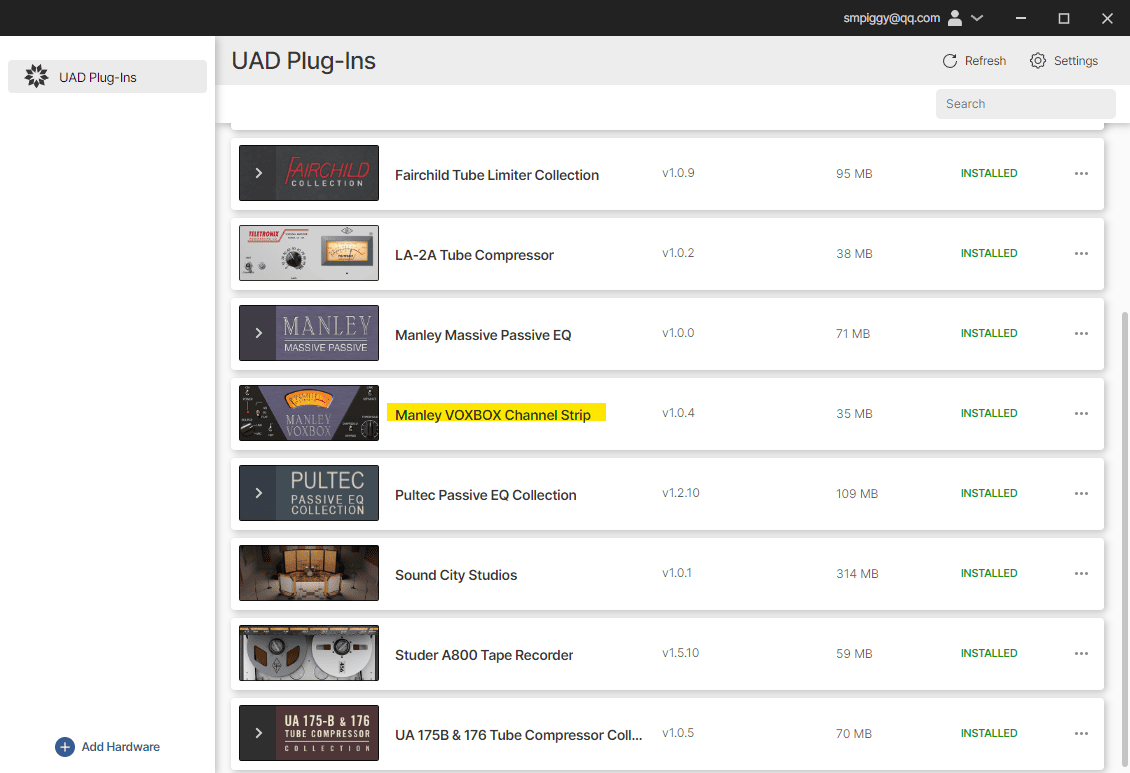
由于使用过Manley Massive, 对他旗下的插件有了很大的好感. 在他的Vari-Mu暂时还没有UAD Native版本之前, 我打算先从他的VOXBOX这个人声通道条插件来感受一下结合了EQ和压缩的整体效果. 在切换了几个预置, 并稍加调试后, 我发现, 这确实是一款功能不多不少, 效果立竿见影的人声通道条插件. 不过, Manley的插件都有一个巨大的缺陷, 就是高强度的CPU占用. 这个问题同样不算大也不算小, 在轨道数量较多的情况下, 或载入多个重复VOXBOX的情况下, 会不会成为系统负担, 同样是巨大的疑问. 相比同类型功能更全面(当然很难评判孰优孰劣)的Scheps Omni在前, 很难说我会不会经常性的想到使用它(VOXBOX)
VOXBOX的页面和最后的操作手册会择时翻译为中文

使用终极的全管式人声处理器进行录音与混音
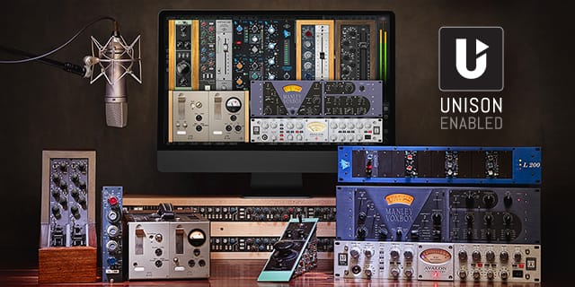
Manley VOXBOX通道条是一个完美的集成了管驱话放, 动态与EQ电路的系统, 为您最重要的人声素材而设计. Manley VOXBOX通道条插件带来了与这台顶级人声通道条同样的对声音的提升与柔顺.

- 用Manley高保真的A级电子管放大, 创造丰满, 奢侈的人声
- Manley拥有33个可选频点的Pultec风格被动EQ, 更方便声音塑形
- 以最完美的启动与释放组合来切入信号
- 为优化贝斯, 木吉他, 人声, 旁白等而匹配的A级EQ和压缩
- 无可匹敌的去齿音/限制器区域能有机的驯服嘶音齿音
- 通过Apollo与Unison™技术, 使用Manley VOXBOX实现实时录音

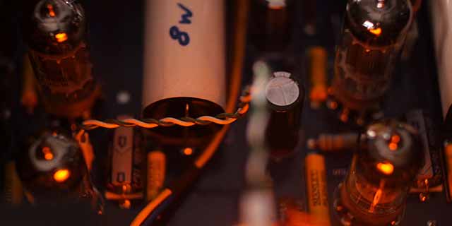
获得Manley的旗舰级硬件之声
Manley VOXBOX通道条插件从头到尾的模拟了当今的精品硬件, 包含高保真的管式话放, Vactrol光电压缩, Pultec式被动EQ, 和去齿音/限制器, 给你一种干净, 细节满满, 充满生命力的热榜之声.
加入魔法般的EQ塑形
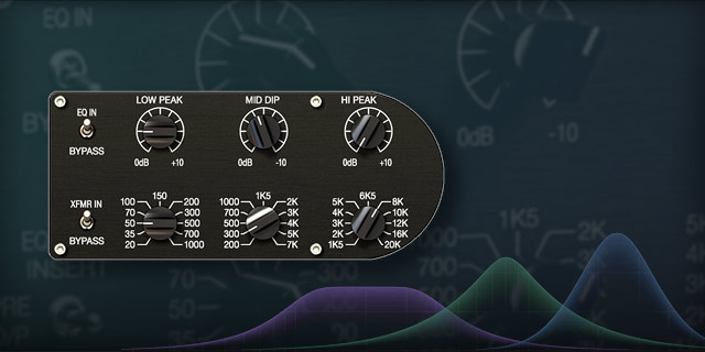
Manley VOXBOX通道条插件的三段式被动EQ, 基于经典的Pultec MEQ-5, 但进行了扩展, 给你一个既让高频甜美, 又让低频定位, 即使在极限的增切下依然保持自然声音的全能EQ.

进入话放前即压缩声源
和硬件一样, Manley VOXBOX插件用它完美调谐的灵活的光电压缩, 让声音瞬态在进入话放之前就得到驯服. 再结合庞大的互动式启动与释放的结合可能性, 你能每一次都获得意料之外的平滑声轨.
得到终极透明的去齿音和限制
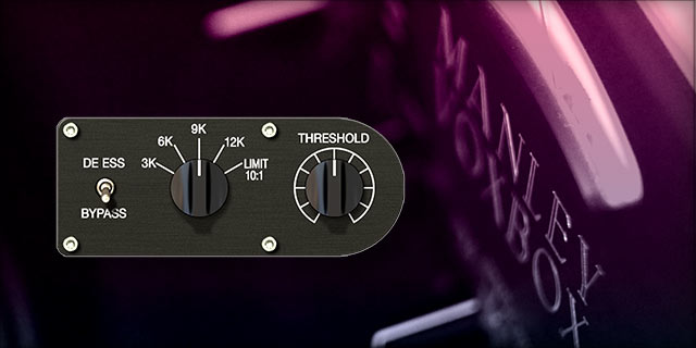
At the center of the Manley VOXBOX的核心, 是它提升过的, 自然声感的去齿音. 仅用两个旋钮, 你就能获得对不止人声, 还有尖锐电吉他, 或过度明亮的吊顶声的完全控制. 你还可以关掉去齿音频率控制, 从而让这个区块变成一个激进, 充满色彩的限制器.
用于任何声源都能获得专业结果
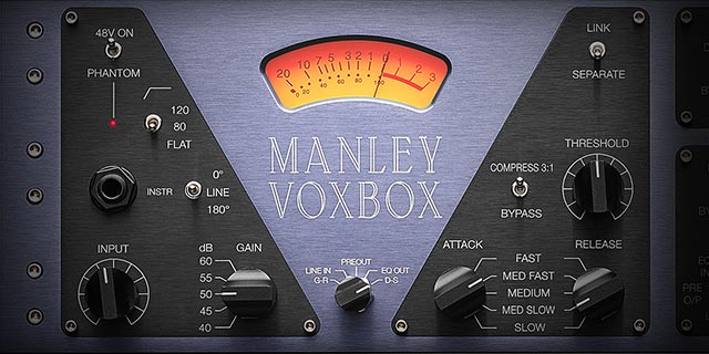
多年以来, Manley VOXBOX因其对高端电子管信号流的控制及光滑的EQ和压缩功能, 都是贝斯手所追寻的秘密武器. Manley VOXBOX也因其一贯的音乐性及对任何声源超越传统的提升, 对静音电吉他, 弦乐和鼓组同样完美.
用Apollo”打通”使用精品管式话放录音的通道
UA开创性的Unison技术, 得以通过Apollo接口利用Manley VOXBOX进行声轨的实时录制, 以获得原始精品硬件的线路/话筒放大器阻抗, 增益台级的”甜美点”, 和别无二致的电路行为.
实际运用中, 单进程的VOXBOX的CPU占用率高达8%, 而Scheps Omni仅为4%, 同时前者会占用2ms的延迟, 而后者完全没有. 这当然有可能是Manley为达到独特的算法而付出的牺牲, 但音质和效率在不同情况下, 都可能成为最重要的考量.
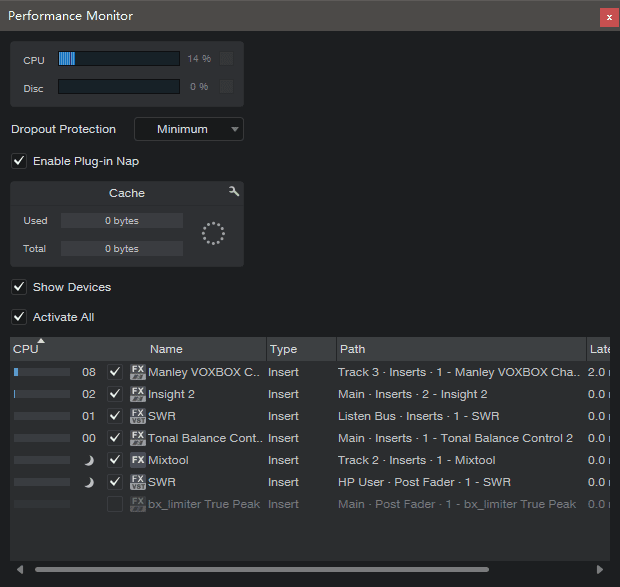
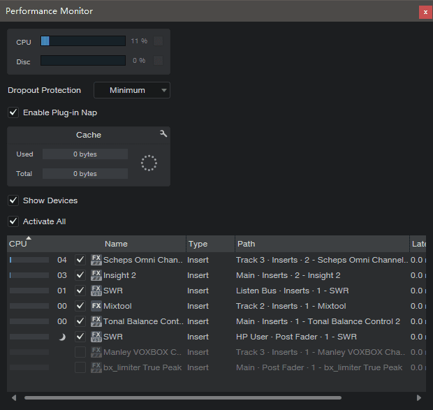
Omni CPU占用及延迟

Manley VOXBOX Channel Strip 用户手册
在此议题中
- Manley VOXBOX Channel Strip 界面
- Manley VOXBOX Channel Strip 控制
- 补充信息
Manley VOXBOX Channel Strip 界面
操作总览
在此区块会提供一个对VOXBOX操作概念的常规总览. 对于更指定的独立控制细节, 请参阅Manley VOXBOX通道条控制.
信号流
一个简化模式的插件信号流展示于下方. 理解此信号流能帮助你获得更可预期的结果. 注意不同于大部分通道条, 尽管此插件的压缩控件位于话放控件的右侧, 然而其压缩电路实际位于话放之前.

控制分组
协同类控件按照处理功能分组, 如下文. 一个值得注意的例外是变压器输出选项(XFMR开关). 尽管此选项开关位于EQ控件区域, 但于电路中, 变压器位于所有电路之后.
VOXBOX界面中的控制组
压缩器
VOXBOX压缩器基于一个由最少量组件组成的被动式光电隔离器电路. 光电隔离期具备动态响应特征, 能在输入音频信号时营造音乐感的愉悦(UA最受欢迎的LA-2A压缩就基于光电隔离器).
光电隔离器不会增加可测量出的失真或噪音, 且插入的损耗仅为0.1dB. Manley的全被动电路, 和位于话筒放大器电路之前的压缩器, 在信号被压缩时也仅创造出极低的本底噪音.
压缩比率则是程序依赖且非线性的, 不过对照VCA式压缩器, 它的压缩比约在3:1. 由于此压缩器位于话放之前, 它并不包含传统的增益补偿控制. 输入, 增益阈值, 输出控件可综合调谐以进行补偿.
压缩器中的增益减量可通过VU表观察.
前置话放
VOXBOX前置话放使用全管式放大电路以获得增益. 注意INPUT输入控制是首要的”干净”式输入控制. 带级数的GAIN增益控制并不简单的调整放大的量级, 而是可以调整放大电路中的负反馈.
除了基础的增益, 负反馈还会影响瞬态反应, 谐波结构, 削波, 和其他声学特性. 由此, GAIN通常被作为染色控制, 而INPUT和/或OUTPUT控制可用作信号电平的标准化.
均衡器
VOXBOX EQ来源于Pultec MEQ-5中段均衡器. Manley通过添加额外的频段, 拓展了MEQ-5的性能, 得到全频段的声学控制.
有三个EQ频段可用, 每段带有11个可选的中心频率. 低频段和高频段提供10dB的提升, 中频段提供10dB的削减.
EQ电路纯100%被动. 每个频段仅在音频路径中包含一个电容, 一个电阻, 一个导电塑胶罩, 和一个金质触点开关, 以保持信号的原始品质. 在EQ电路中不包含任何电子管, 晶体管和其他主动式组件.
去齿音 / 限制器
在EQ电路之后, 是第二个光电隔离限制器. 一个被动的深切式滤波器位于限制器的动态侧链控制中, 以启用针对高频的去齿音功能.
侧链中的深切式滤波可从四个嘶音频率中选择. 侧链滤波可通过关闭, 由去齿音转变为第二个限制器. THRESHOLD可作用于控制去齿音或限制器的输入量..
限制器的压缩比率为10:1(比率有时也依赖于程序), 可达到20dB的限制. 去齿音中增益减量的量级可在VU表中观察.
无标记控制
在控制模式(如果DAW支持)中观察, 会发现有些控件的数值是从0到10连续式的. 如同硬件一样, 这些控件没有绝对数值标记, 目的在于通过用户耳朵来选择更适合的数值.
艺术家预置
插件版包含了一些杰出VOXBOX用户的艺术家预置.
Manley VOXBOX Channel Strip 控制
前置话放控制
SOURCE 声源
声源的旋钮式开关提供了输入信号的衰减The SOURCE rotary switch provides an attenuation pad for the input signal. When set to MIC, the input signal is not attenuated. When set to LINE, the input signal is attenuated by approximately 4 dB.
Tip: Click the LINE or MIC text labels to select the source value.
LOW CUT
The Low Cut (high pass) filter for the Mic, Line, and Hi-Z inputs is available via this three position switch. Available filter cutoff values are 120 Hz (up position) and 80 Hz (middle position). When set to FLAT (down position), the filter is bypassed.
The Low Cut filter has a gentle slope of 6 dB per octave with minimal phase shift. Low Cut is typically used to eliminate rumble and/or other unwanted low frequencies from the input signal.
Tip: Click the 120/80/FLAT text labels to select a filter value.
POLARITY
The Polarity switch affects the Mic, Line, and Hi-Z inputs. When in the 0° (up) position, the input signal polarity is normal. When in the 180° (down) position, the polarity of the input channel’s signal is inverted.
Polarity inversion can help reduce phase cancellations when more than one microphone is used to record a single source.
Tip: Click the text label to select the desired setting.
INPUT
INPUT is the main level control at the input to the plug-in. It attenuates the signal before the compressor and preamplifier.
The available range is 0 to 10 but values are arbitrary. Rotate the knob counter-clockwise to decrease the signal level.
GAIN
This five-position switch sets the amount of negative feedback in the mic preamp (it is not a pad or simple gain control). Negative feedback affects the transient response, harmonic structure, clipping, and other sonic characteristics of the preamp. As such, it is typically used as a tone control.
GAIN values of 40, 45, 50, 55, and 60 dB are available.
Tip: Click the GAIN text labels to select the value.
Compressor Controls
Note: Unlike most channel strips, the compressor circuit is located before the preamp circuit.
SIDECHAIN LINK
When the plug-in is used in a stereo-in configuration, this switch allows the dynamics processors of both channels (left & right) to always be compressed in equal amounts or completely independently. When used in a mono-in configuration, this switch is locked in the LINK position.
Tip: Click a text label to select the desired setting.
Note: This function applies to both the main compressor circuit and the de-esser/limiter circuit.
LINK
When set to LINK, the amount of compression is always the same for both channels. Stereo imaging at the input is maintained by preventing left-right shifting at the output when one channel has higher signal peaks compared to the other channel.
SEPARATE
When set to SEPARATE, the amount of compression occurring is completely independent in both channels.
Note: If one channel has higher signal peaks than the other channel, the left-right imaging may shift at the output.
COMPRESSOR BYPASS
When this switch is in the COMPRESS 3:1 (up) position, the passive opto-isolator compressor circuit is engaged. When in the BYPASS (down) position, the circuit is disabled and the other compressor controls have no effect.
Tip: Click a text label to select the desired setting.
When the compressor circuit is bypassed, processor usage is reduced. On the UAD-2 plug-in, if UAD-2 DSP LoadLock is inactive, UAD DSP usage is reduced.
THRESHOLD
This continuously variable control, which is located after the INPUT control in the circuit, determines the amount of compression to be applied to the input signal. Rotate THRESHOLD clockwise to lower the threshold and increase compression. Signals below the threshold are not compressed.
ATTACK
ATTACK sets the amount of time that must elapse after the input signal reaches the THRESHOLD level before compression is applied. Five rates are available: Slow, Medium Slow, Medium, Medium Fast, and Fast.
Tip: Click near the left of the value label to select the value.
The faster the attack, the more rapidly compression is applied to signals above the threshold. Slower attacks allow a signal’s attack transients (for example, the pluck of a string) to pass without compression, which can produce a punchier sound.
Unlike typical compressors, slower RELEASE settings with VOXBOX will make ATTACK changes more obvious. VOXBOX is noted for the unusual way the attack ‘rides’ above the reduction set by the release.
RELEASE
RELEASE sets the amount of time that must elapse after the input signal drops below the THRESHOLD before compression processing is ceased. The release time slows as gain reduction approaches 0 dB; this behavior is a function of the opto-isolator.
Note that due to interactivity in the passive circuitry, RELEASE has some effect on attack rates.
Tip: Click near the right of the value label to select the value.
Five rates are available: Slow, Medium Slow, Medium, Medium Fast, and Fast. Each release setting is carefully tuned for specific time constants, as described in the table below.
| Rate Setting | Time (seconds) | Notes |
| Slow | 5.0 | Very slow release for the most inaudible compression |
| Medium Slow | 2.0 | Typical choices for vocals |
| Medium | 1.0 | Much like old LA-2A’s but also tuned for drums and bass. Works well with dynamic broadcast audio. Pumps a bit when Attack is set to Slow. |
| Medium Fast | 0.5 | |
| Fast | 0.3 | Mimics the Manley Electro-Optical Limiter and works best in the range of 3 to 8 dB of compression |
Compressor release times
Equalizer Controls
EQ BYPASS
When this switch is in the EQ IN (up) position, the passive equalizer circuit is engaged. When in the BYPASS (down) position, the circuit is disabled and the other EQ controls have no effect.
Tip: Click the text label to select the desired setting.
When the EQ circuit is bypassed, processor usage is reduced. On the UAD-2 plug-in, if UAD-2 DSP LoadLock is inactive, UAD DSP usage is reduced.
LOW PEAK
This continuous knob sets the amount of low EQ band gain applied to the LOW FREQUENCY value. The available range is 0 to 10 dB.
LOW FREQUENCY
This rotary switch determines the frequency of the equalizer’s low band. Eleven values are available (Hz): 20, 35, 50, 70, 100, 150, 200, 300, 500, 700, and 1000.
Tip: Click the text label to select the desired frequency.
Note: This switch has no effect when LOW PEAK is set to 0 dB.
MID DIP
This continuous knob sets the amount of mid EQ band cut applied to the MID FREQUENCY value. The available range is 0 to -10 dB.
MID FREQUENCY
This rotary switch determines the frequency of the equalizer’s mid band. Eleven values are available (Hz, kHz): 200, 300, 500, 700, 1.5K, 2K, 3K, 4K, 5K, and 7K.
Tip: Click the text label to select the desired frequency.
Note: This switch has no effect when MID DIP is set to 0 dB.
HI PEAK
This continuous knob sets the amount of low EQ band gain applied to the HIGH FREQUENCY value. The available range is 0 to 10 dB.
HIGH FREQUENCY
This rotary switch determines the frequency of the equalizer’s high band. Eleven values are available (kHz): 1.5K, 2K, 3K, 4K, 5K, 6.4K, 8K, 10K, 12K, 16K, and 20K.
Tip: Click the text label to select the desired frequency.
Note: This switch has no effect when HI PEAK is set to 0 dB.
De-Esser / Limiter Controls
DE-ESS BYPASS
When this switch is in the DE ESS (up) position, the de-esser/limiter circuit is engaged. When in the BYPASS (down) position, the circuit is disabled and the other de-esser/limiter controls have no effect.
Tip: Click the text label to select the desired setting.
When the de-esser circuit is bypassed, processor usage is reduced. On the UAD-2 plug-in, if UAD-2 DSP LoadLock is inactive, UAD DSP usage is reduced.
DE-ESS SELECT
This rotary switch defines the center frequency of the dynamic control sidechain notch filter. Four sibilant frequencies are available (kHz): 3K, 6K, 9K, and 12K. The value is typically set to the center of the undesirable frequency range to be reduced.
When set to LIMIT 10:1, the sidechain notch filter is bypassed and the circuit behaves as an electro-optical limiter.
Tip: Click the text label to select the desired value.
DE-ESS / LIMITER THRESHOLD
THRESHOLD controls the amount of de-essing or limiting by defining the signal level at which gain reduction is activated. Rotate the knob clockwise to lower the threshold and increase de-essing/limiting.
Global Controls
VU METER
The VU Meter displays average signal levels at several key points in the circuitry as well as gain reduction amounts in the main compressor and de-esser/limiter circuits. The displayed signal level is set with the METER SWITCH.
Note: The VU Meter displays average loudness and does not display signal peaks.
METER SWITCH
This switch determines which signal is displayed in the VU Meter.
Tip: Click the text label to select the desired value.
G-R (default setting)
Displays the amount of gain reduction occurring in the main compressor circuit.
LINE IN
Displays average loudness at the input to the plug-in when SOURCE is set to LINE.
PREOUT
Displays average loudness at the output of the preamplifier circuit.
Note: The VU Meter does not display levels at the output of the plug-in.
EQ OUT
Displays average loudness at the output of the equalizer circuit.
D-S
Displays average loudness at the output of the de-esser/limiter.
TRANSFORMER BYPASS
When this switch is in the XFMR IN (up) position, the output signal is routed through the output transformer and the signal is slightly colored. When in the BYPASS (down) position, the transformer is bypassed and the signal is routed directly to the output.
In the original hardware unit, the transformer is in the balanced output circuit connection and the unbalanced output connection bypasses the transformer. In the digital realm, this switch conveniently provides both options.
Tip: Click a text label to select the desired setting.
When the transformer circuit is bypassed, processor usage is reduced. On the UAD-2 plug-in, if UAD-2 DSP LoadLock is inactive, UAD DSP usage is reduced.
OUTPUT
OUTPUT is a clean digital gain control that adjusts the signal level at the output of the plug-in. The available range is -60 dB to +12.0 dB.
Tip: Click the “0” text label to return the value to 0 dB.
This control, which does not exist on the original hardware, facilitates the ability to maintain unity gain and/or maximize color of the overall signal. For example, compression and EQ can be adjusted to taste, while using OUTPUT to normalize levels.
POWER
The is the plug-in’s overall bypass control for comparing the processed and unprocessed signal. In the ON (up) position, signal processing is active. In the down position, the unprocessed signal is heard.
Tip: Processor usage is reduced when the POWER is off. UAD-2 DSP usage is reduced when the POWER is off if DSP LoadLock is disabled in the Configuration panel within the UAD Meter & Control Panel application.
READY LED
The READY LED, located below the POWER switch, illuminates three seconds after powering on. In the original hardware, the LED indicates the unit is ready for use. In the plug-in, this behavior is a cosmetic emulation only. The plug-in is fully functional when it is instantiated and/or enabled.
Additional Information
The original user manual written by Manley Labs for the hardware unit contains a wealth of great information about the philosophy, design decisions, and use of the VOXBOX. It is highly recommended reading for those interested in technical details. The manual can be found on the Manley website, along with info about their other great products.
购买凭证
